The Bonded Block Model (BBM) in 3DEC can be used to simulate a rock mass as bonded polyhedral elements (e.g., tetrahedrals). These bonded polyhedral blocks can break apart along their subcontacts (bonds) as a result of stress concentrations, mimicking the initiation of cracks that can coalesce and/or propagate to fracture the rock mass. Joints may also be explicitly represented by overprinting them as cuts on the intersecting blocksThis results in an emergent damage pattern with associated bulking.
The 3DEC approach differs from particle-based methods such as PFC3D in its inherent ability to represent a zero initial porosity condition, as well as interlocked irregular block-shapes that provides resistance to block rotation (moments) after contact breakage. This approach matches the high uniaxial compressive strength (UCS) to tensile strength ratios and friction angles typically exhibited by hard rock. The strength of the contacts between the tetrahedral blocks forming the BBM are directly informed by randomly sampling the cumulative tensile strength distribution derived from a point load test campaign. The cumulative strength distribution is used to account for strength heterogeneity. The cohesion of the contacts is set to be a multiple of the assigned tensile strength such that the ratios produced a macro UCS to tensile strength ratio is of the order of 10–20. The blocks themselves are treated as an elastic medium.
These processes tend to dominate the rock mass behaviour in low confinement zones near excavations. Additionally, 3DEC allows for joints to be explicitly represented by overprinting them as cuts on the intersecting blocks.
This specimen is created using the rblock construct command. This command takes a geometry set and meshes it, creating a zero porosity packing of rigid blocks. The rigid blocks are then scaled so that they initially overlap. This is important for BBM modeling as, when rigid blocks are bonded, the computed contact location is only incrementally updated. In other words, the contact location does not respond to changes in the overlap region. Instead, one can conceive of the contact location as the location of an element of glue that is fixed to the surfaces of the rigid blocks until failure.
To dramatically increase computational performance, the rigid blocks are rounded with the rblock erode command. This command reduces the core shape and introduces rounding. This operation is important for rigid block modeling with zero porosity initial packings as the erosion removes many vertex-vertex and edge-edge contacts in the sense that they will be inactive. In fact, in this model with ~7700 rigid blocks there are ~13,000 face-face contacts between rigid blocks whereas there are more than 225,000 vertex-vertex and edge-edge contacts. These contacts contribute negligibly to test results but increase the computational time dramatically. In this model such contacts are inhibited with the contact inhibit command, meaning that they are skipped from all computations. If one were interested in very large strain where these contacts may be important, one could easily hook up a FISH function to the bond_break event and activate all or some subset of the contacts around the rigid blocks on each side of the contact.
Advantages over other discontinuum approaches:
- Ability to represent a zero initial porosity condition
- Interlocked irregular block shapes that provides resistance to block rotation (moments) after contact breakage
- High uniaxial compressive strength to tensile strength ratios and friction angles
Advantages over continuum approaches:
- Exhibits spalling behavior
- Unidirectional bulking possible upon breakage
- Cracks can initiate, propagate and/or coalesce resulting in associated fragmentation
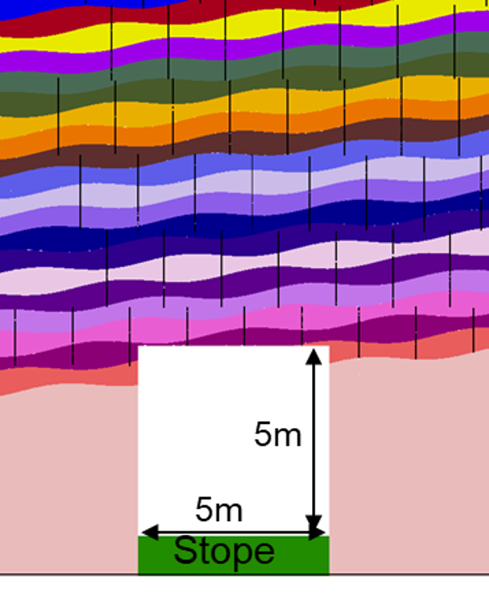
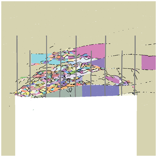
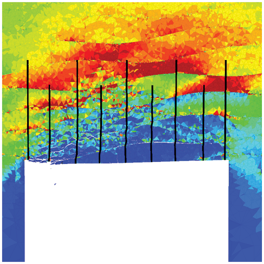
The following is an example of BBM modeling where a 3DEC model of a 5 m wide mine drift 440 m deep. The simulations predict the response of the tunnel and a particular ground support regime (#7 rebar) after a nearby stope has been excavated (Garza-Cruz et al., 2019).